Introduction
The purpose of Lab 3 was to equip the Artemis Nano with two Time of Flight (ToF) sensors, which work together to relay distance information to the robot.
Prelab
The ToF sensor used in this class is the Sparkfun VL53L1X. According to the datasheet , the default I2C address is 0x52. Using both the sensors at the same time would therefore pose an issue, unless if the address is changed programmatically, or if the XSHUT pin on the sensor's PCB is used. The XSHUT pin shuts down the sensor when a digital LOW signal is sent to it, and turns it back on with a digital HIGH. I chose to use a combination of both approaches, where I shut down one sensor, changed the address of the other, and turned the first sensor back on as I found it to be the most straight forward. I will discuss this in more detail in the ToF Sensors in Parallel section below.
Additionally, the datasheet mentions that the diagonal FOV is "programmable from 15 to 27 degrees", and that the maximum range is 400 cm. By placing the two ToF sensors on the front of the robot in a front-headlight formation, almost all obstacles in the front should be able to be detected and avoided, even while turning. The only area of concern is the back if the robot is reversing.
Lab Tasks
Wiring the ToF Sensor
The first task was to connect the ToF sensor to the Artemis Nano. This required soldering a Sparkfun QWIIC cable to the ToF sensor PCB so that there is an interface to connect the sensor. I first made a wiring diagram for which wires from the QWIIC cable goes to which through-hole on the sensor PCB, as can be seen below.
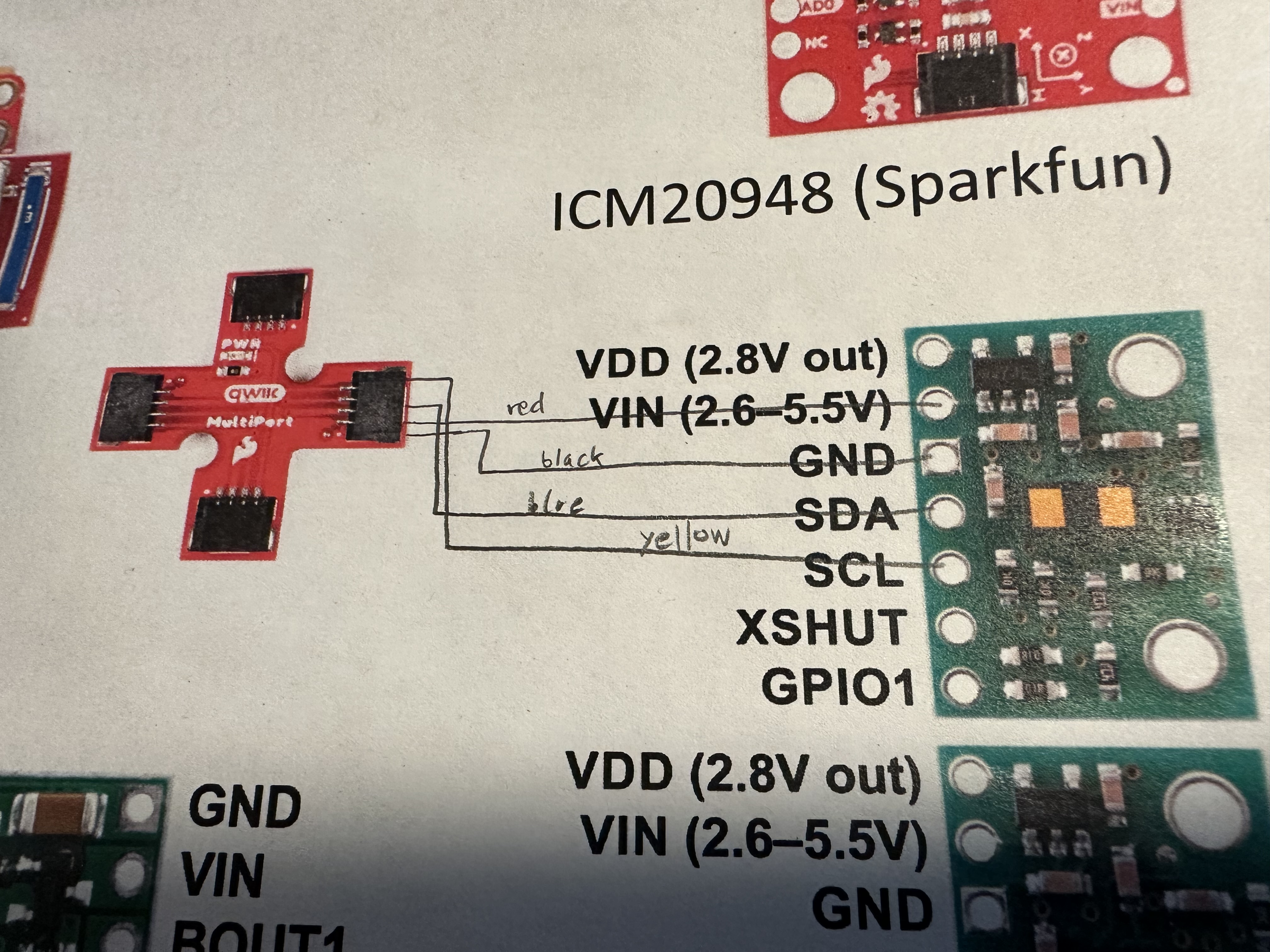
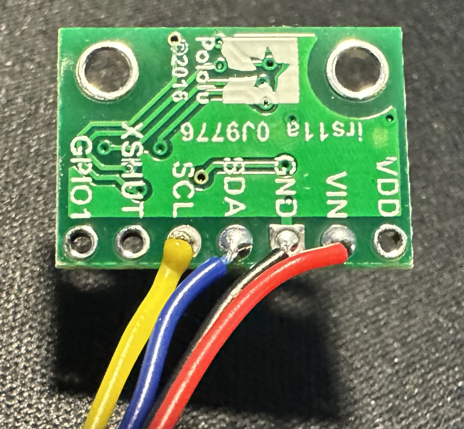
Using this diagram as a reference, I soldered the red, black, blue, and yellow wires from the QWIIC cable to the Vin, GND, SDA, and SCL through-holes respectively. I also made sure to choose the longer cables since the sensors might need to far away from the Artemis board when attached to the robot. Here is what it looks like after soldering:
I2C Scanning
The next step was to find the sensor on the example code. First, I used the breakout board, which has allows up to three QWIIC connections to the Artemis board, to connect the sensor. Then, I flashed the code from Example5_Wire_I2C.ino to the board. As can be seen in the Serial Monitor screenshot below, the sensor was found at address 0x29.
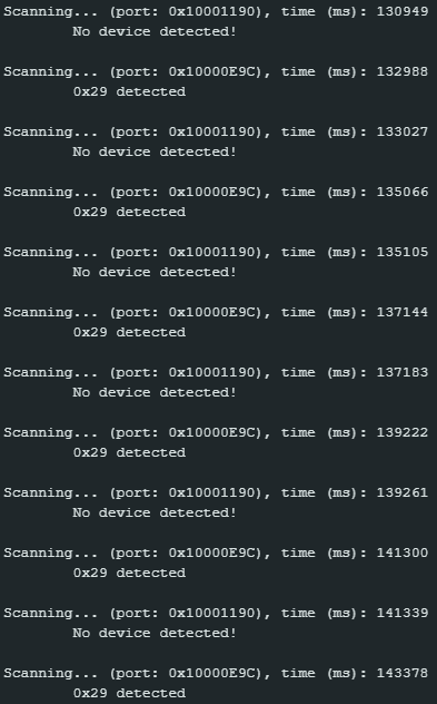
Evidently, this contradicts the datasheet, which mentioned that the sensor's address was 0x52. This is because the right-most bit of the 0x52 address is a read/write bit, and the Artemis shifts the address to the right by one bit, thereby resulting in 0x29.
Sensor Data
After establishing a connection between the Artemis board and the ToF sensor, I tested the sensor's accuracy, repeatability, and range. I attached a ruler to the table and placed the white box that stores the lab materials on the 0mm mark. Then, I held the sensor at various distances from 0mm and took 2034ms worth of data, which resulted in 21 measurements from each distance. The plot below summarizes this data.
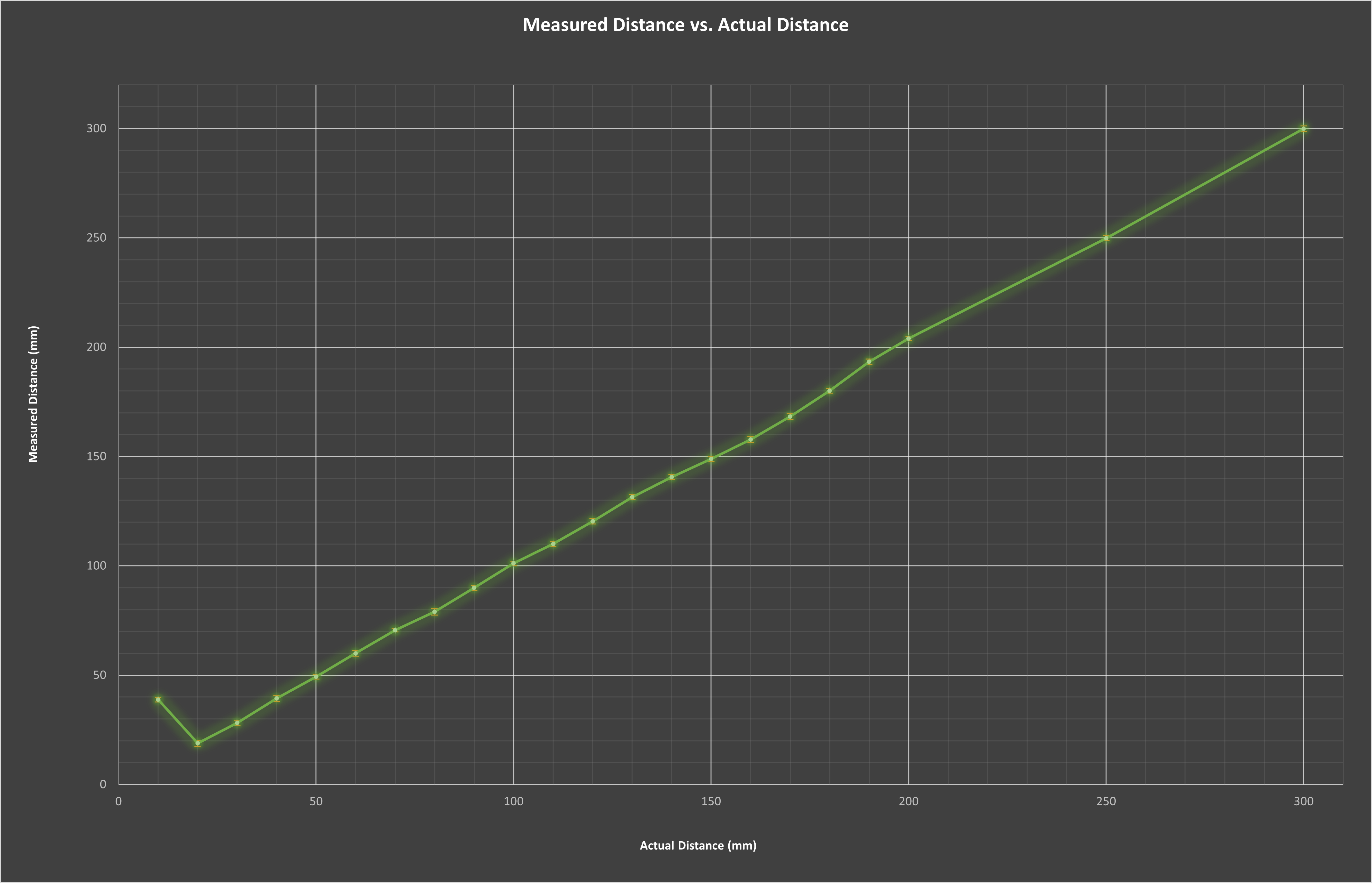
As evident from the graph, the range of the sensor was from about 20mm to 300 mm, to the extent that I tested it. I was not able to verify the 4m claim, as I did not have a 4m long ruler to add as the actual distance. Regardless, the takeaway is that the sensor cannot measure something too close to it.
With regards to accuracy, each data point on the plot is the average of the 21 measurements, and evidently most of them, with the notable exception of 10mm, are accurate. The line segments that connect all of the data points together is almost fully linear. Additionally, with regards to repeatability, the standard deviations are also plotted for each data point. Evidently, the orange error bars are very small, and the largest standard deviation was 1.5mm, demonstrating that the data was precise and repeatable.
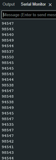
Finally, the sensor was also tested for ranging time. This was done by recording the time before the startRanging() function was called, and subtracting it from the time after the data was ready, distance was recorded in a variable, interrupts were cleared, and the stopRanging() function was called. As evident from the screenshot of the Serial Monitor below displaying ranging time in microseconds, it took an average of about 96.5ms.
ToF Sensors in Parallel
After performing all of the tests, it was finally time to connect the second ToF sensor and obtain distance data from both sensors simultaneously. As mentioned in the prelab, this required a connection from the XSHUT pin on one of the sensors to a GPIO pin on the Artemis. Hence, I soldered a green wire to Pin 8 as can be seen in the picture below.
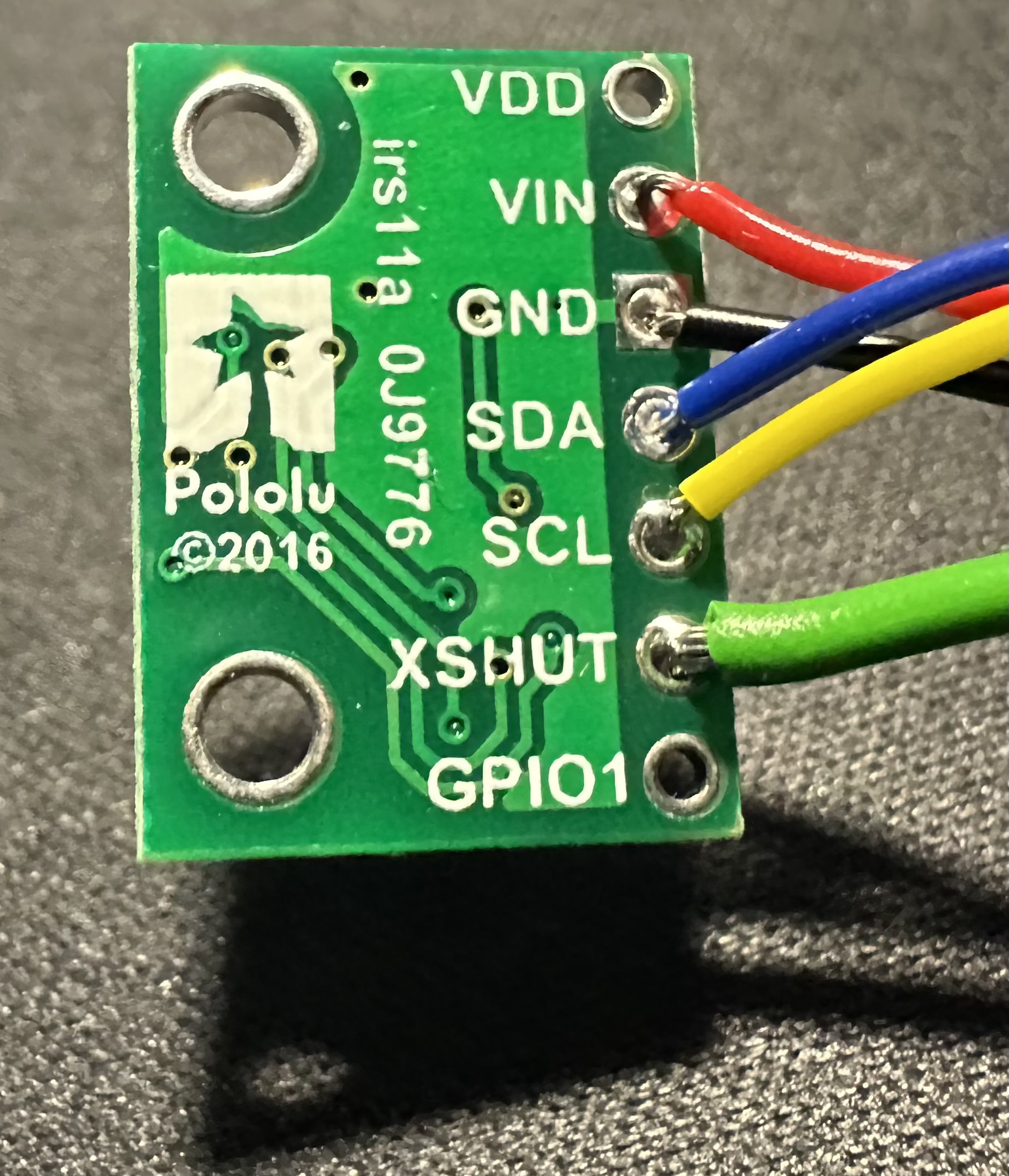
Then, I connected both the sensors to the breakout board and connected it to the Artemis, as can be seen in the picture below.
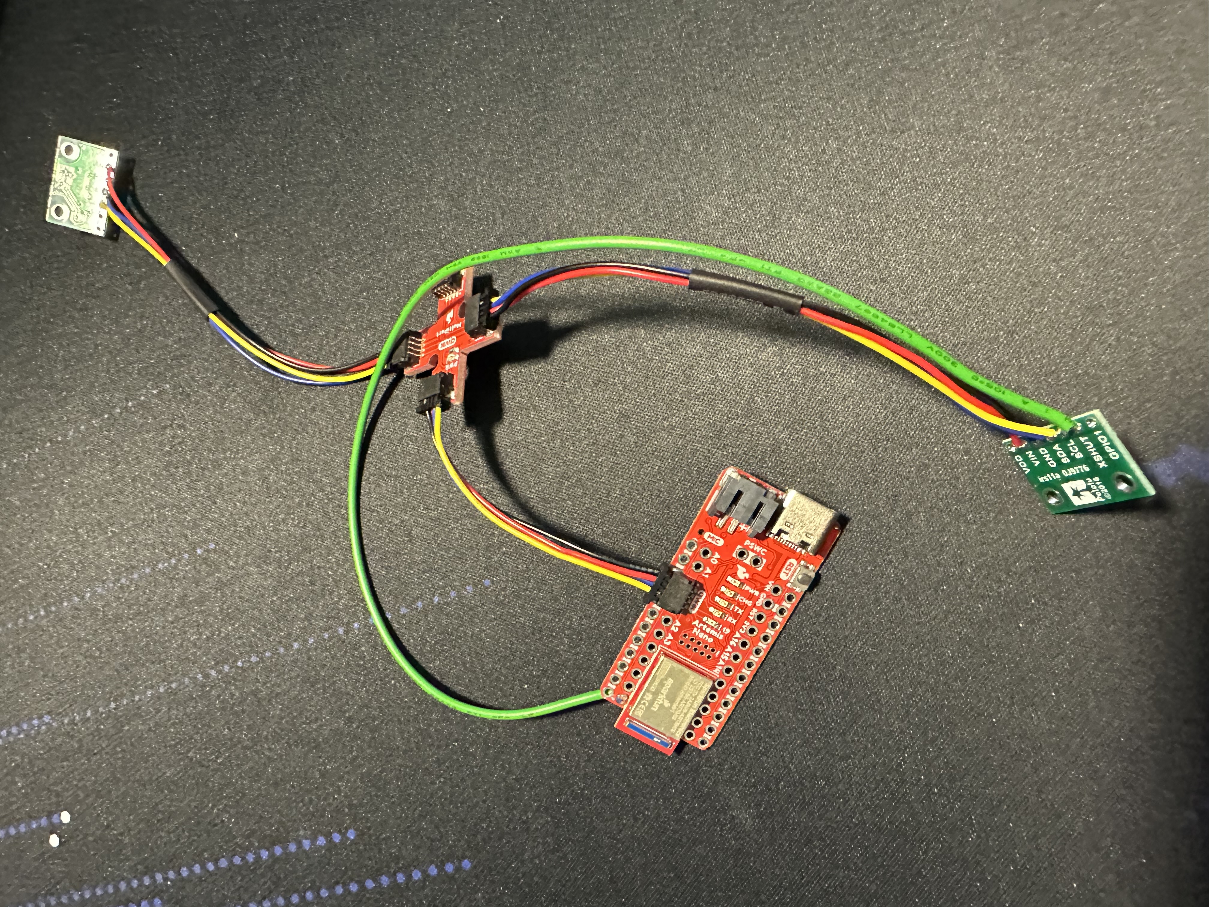
With the help of Joseph Horwitz, I took the combination approach of using the shutdown pin and programmatically changing the I2C address. As can be seen in the code snippet below, I first shut down one of the sensors, changed the address of the other to 0x22, and turned the first sensor back on. This way, there needed not be any interruptions in the loop where the distance data was collected, which might have resulted from taking data from one sensor, turning it off, and taking data from the other sensor.
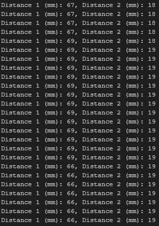
Using this code, I recorded data from both sensors. At first, there was some difficulting displaying them, but with a new QWIIC breakout board, both sensors relayed their distance information, as can be seen in the Serial Monitor screenshot below.
ToF Sensor Speed
To ensure that the code does not wait for a delay or a while loop, resulting in the waste of precious CPU cycles, I added boolean variables containing whether or not a measurement was currently being taken. If this value was false, I would call the startRanging() function and set the boolean variable to true. On every loop cycle, if the data was ready to be recorded, I would set the boolean variable back to false, record the distance information in an integer variable, clear interrupts, and call the stopRanging() function. This way, there would be no need to use a while loop to wait for the data to be ready. This can be seen in the code snippet below.
Sending ToF Data over Bluetooth
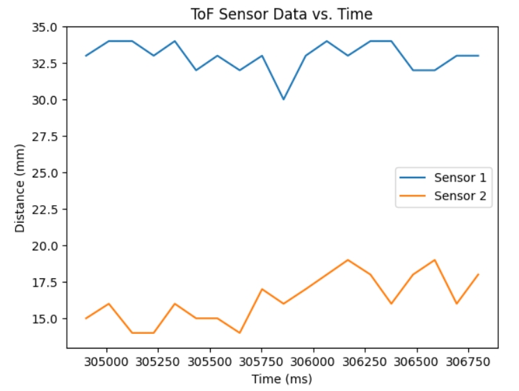
For the final lab task, I sent distance data from both ToF sensors over Bluetooth. The plot below shows the data received in mm vs. the time in ms.
