Introduction
The purpose of Lab 5 was to control the RC car using the Artemis directly, using the newly added dual motor drivers. By the end of the lab, the car can execute a set of pre-programmed moves including turns.
Prelab
Before coming to the lab, there were a few things to consider. Firstly, I considered the pins that I would use to connect the motor drivers to. Given that they require PWM signals, the pin would have to be labeled with a "~" in the datasheet. Also, taking into consideration how they would be oriented to allow for easier connections, I decided to connect the motor drivers as can be seen in the image below, where the left and right motor drivers are on either side of the Artemis board.

For the left motor, I decided to connect IN1 and IN2 to A15 and A16, respectively. For the right motor, I decided to connect them to A1 and A0, respectively. The OUT1 for both drivers would be connected to the negative of the motor and the OUT2 to the positive. Finally, all of the grounds would be connected, ensuring common ground among all, and the VIN for both drivers would be connected to the motor battery's positive.
Additionally, the Artemis and the motor drivers are to be powered using different batteries. This is because the motors connected to the motor drivers draw a lot of current, while the Artemis does not. Hence, the 850mAh battery is used for the motor drivers, and the 650mAh battery is used for the Artemis.
Finally, the last consideration was for routing the variety of wires. As seen in Figure 1, there are about 13 wires that need to be long enough to reach other components. Given the scope of this lab, I decided that it would be fine to have long wires, as long as they are not unnecessarily long to cause considerable noise, as it would make the connections easier, and there would be no requirement to desolder and resolder the wires in the case of a wire not reaching a component. Also, taking inspiration from Anya's report, I decided to twist the wires with each other to cancel out the positive and negative magnetic fields. Furthermore, given that solid core wires can cause problems when undergoing high accelerations, I decided to use stranded wire for all connections.
Lab Tasks
First Dual Motor Driver
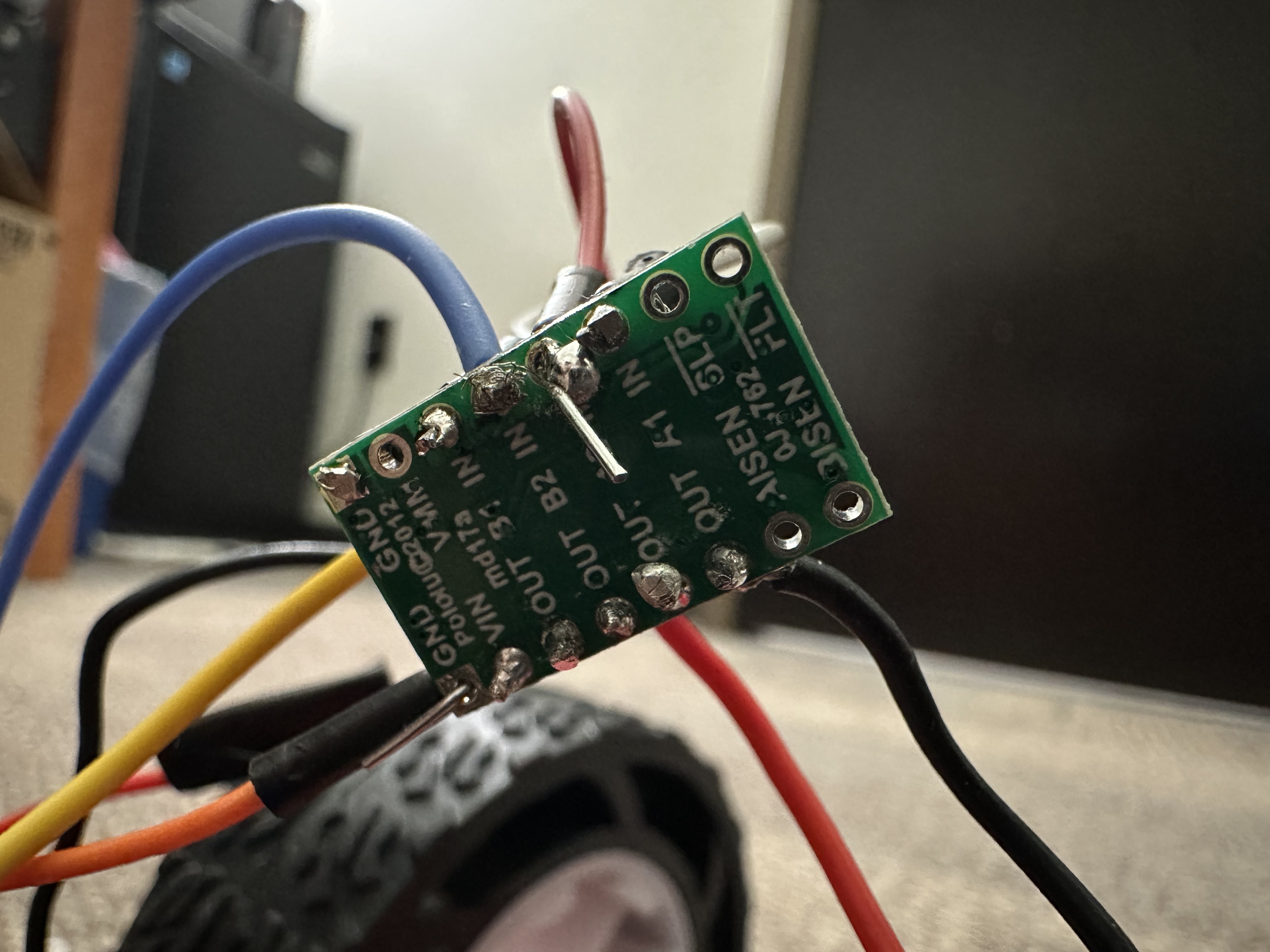
I started by soldering all of the wires to the motor driver. After soldering, here is what it looked like.

Unfortunately, due to timing constraints, I was unable to go to the lab to take oscilloscope measurements for the PWM signals. However, if I were to have had time, I would have chosen the power supply voltage to be 3.7V, as this is equal to the voltage output of the motor battery, and current to be 2A, to be well below the maximum rating.
analogWrite
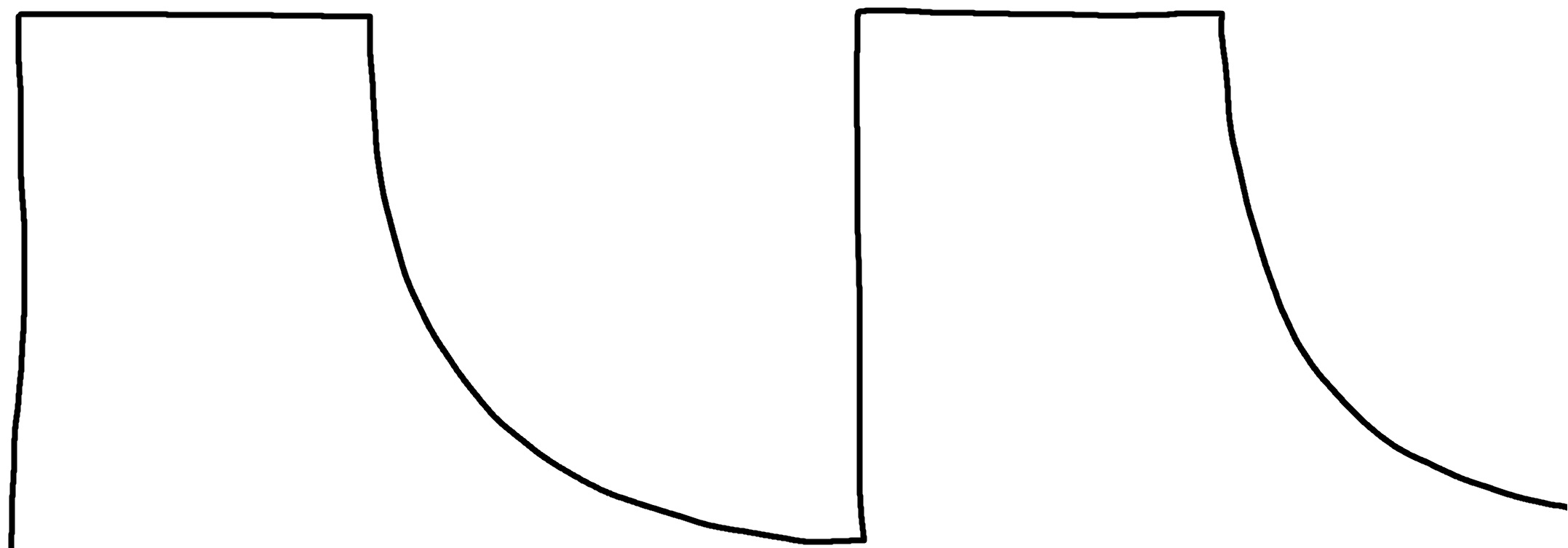
As mentioned above, I was unable to go to lab to get the oscilloscope measurements. However, taking a look at my classmates reports, it seems that the waveform for a 50% duty cycle signal has the following shape.

Taking the Car Apart
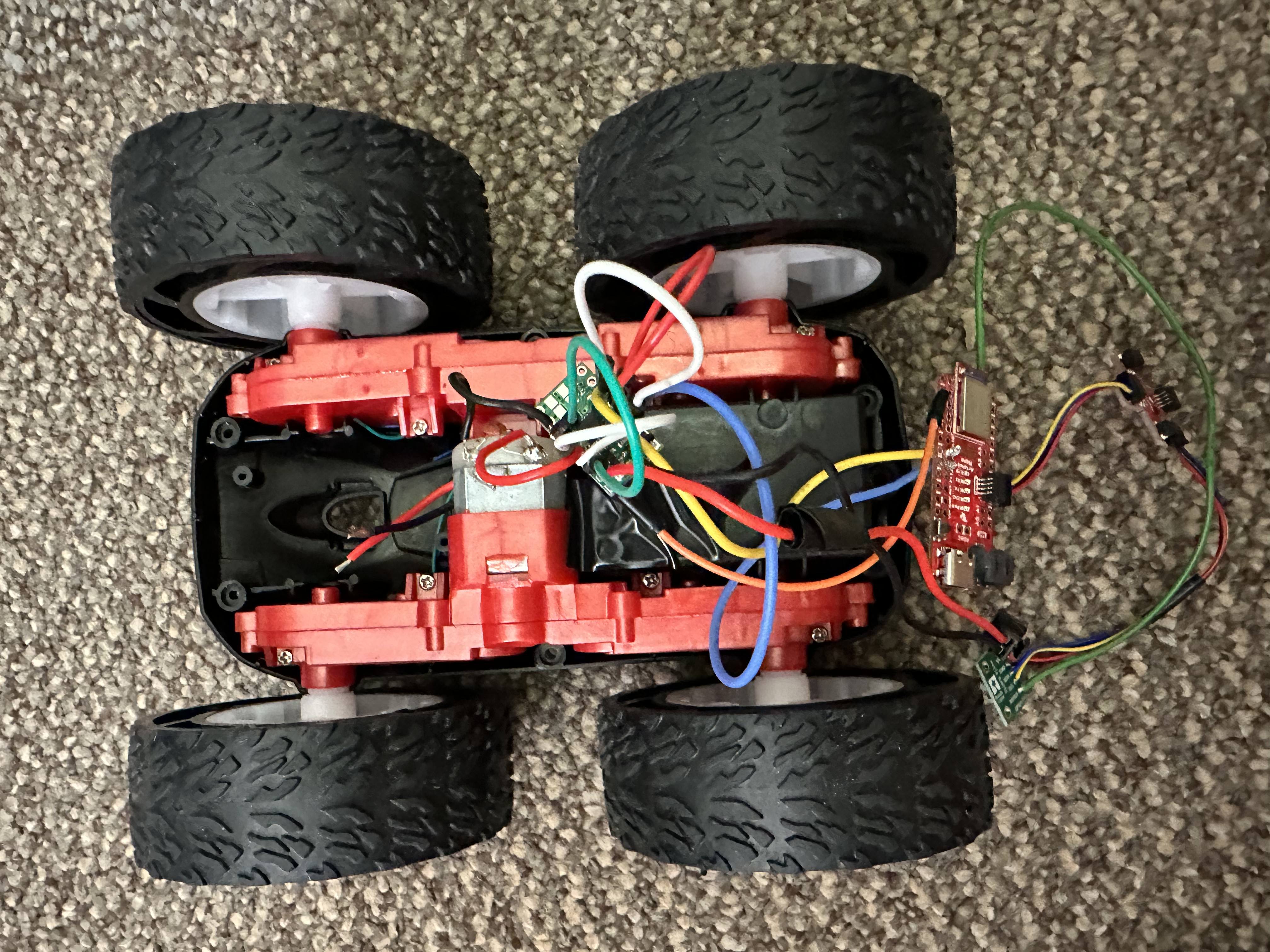
The next step was to take apart the RC car and connect one of its motors to the motor driver. After connecting the motor driver to the motor, the RC car looks like the following.

Free Running the Motors
After connecting the motor drivers and Artemis to the RC car, the video in Figure 5 shows how I ran the motor on one side of the car using the following code.
Powering Motor Drivers with 850mAh Battery
Since I was unable to go to the lab, I have already been using the 850mAh battery to power the motor drivers. I made sure to connect the positive and negative terminals correctly, as well as to connect everything to ground and there were no issues so far.
Second Dual Motor Drivers
The second dual motor driver is where I ran into an issue. I was soldering the wires to the motor controller at home, and initially, everything was fine. However, as I soldered more and more, the soldering iron seemed to perform more and more worse, until it was very difficult for the solder to attach to the solder pads on the through-holes. When soldering the wires to the second motor controller, I could not get the solder to stay and attach the wires to the controller correctly, no matter how long I heated up the soldering iron or placed its tip on the soldering pad. Hence, I was unable to get the second motor driver connected to the RC car and the Artemis. But, given the wiring diagram , I would have connected the second motor driver to pins A0 and A1 on the Artemis, and would have ran the following code for the wheels other side of the car to rotate back and forth.
Full Installation
After experimenting with one of the motor drivers, I would have placed the motor drivers on the underside of the motor battery holder, and placed the Artemis and its battery in the large space in front of the motors. I would have placed the ToF sensors in the front of the car, each angled a little to the left and right. Finally, the IMU would be placed on the underside of the battery holder, so that it stays flat for accurate measurements.
PWM Discussion
Taking a look at the classmates observations, it seems that the lower limit of the PWM value in analogWrite(pin, PWM) was between 40 and 60. It makes sense, as the motor driver is very likely keeping a threshold to be robust against noise that could perhaps cause a 0-signal to appear up to 40, and be mistaked for moving the motors.
Calibration
If my robot did not travel in a straight line, I would have experimented with multiplying one of the sides' PWM value by a factor to make it so that they both travel at the same rate, and thus keep the robot moving in a straight line. I would do this using the following code, changing the factor constant to one that works well.
Open Loop Control of Robot
Since I was unable to use the second motor driver, I cannot show a video of the robot performing the open loop control. However, I would have used the following code to move the robot forward for 2 seconds, turn right 90 deg, move forward 2 seconds, turn left 90 deg, and move forward 2 seconds in a loop.